Raspberry PI
Have you ever wanted to be able to control AC power outlets through your local network or the Internet? We did, and found a use for an old Raspberry Pi in the process. Many people probably have one of the original Raspberry Pi single board computers that they have since replaced with a more powerful model, but for this application an older Raspberry Pi works perfectly well. Of course you could use a newer model, but the pinouts might be a bit different.
Also, it would certainly be possible to build this project using the less expensive Raspberry Pi Zero, though once again the pinouts may not be exactly the same. However, the Raspberry Pi Zero does not have a wired Ethernet port, which may be important for some types of usage. While it may be possible to add a USB Ethernet Adapter, assuming one can find a compatible unit, a possibly better and less expensive approach would be to add a ENC28J60 Ethernet Module. One major downside to using a Pi Zero and an Ethernet Module is that you will need to find a way to keep both units physically separated from each other, and also separated from the relay module and the rest of the wiring, which might require building some kind of custom case. We preferred using an older original model Raspberry Pi, which of course already has a built-in Ethernet connector, and for which we already had a case.
Before we begin, though, please note the following: The title of this article is “How we made a Raspberry Pi controlled 8-outlet power box” and the use of the word “we” is deliberate. Just because we did this doesn’t necessarily mean you should. Here are some reasons you should not do what we did:
1. If you don’t understand that electricity is dangerous and can cause death, serious injury, or property damage, you should not do this.
2. If you have no knowledge of good electrical wiring practices, or if you would call an electrician to replace a defective light switch or outlet, you should not do this. If you want to learn good electrical wiring practices, we recommend the latest edition of the book “Wiring Simplified” by Frederic P Hartwell and Herbert P. Richter. It is updated for each new edition of the National Electrical Code and explains how to correctly wire switches, outlets, light fixtures and so on.
3. If you are the type of person who cannot accept responsibility for your own actions and mistakes, and would even think of suing someone else because you did not know what you were doing and injured yourself or burned down your house, you most definitely should not do this. The authors specifically disclaim any responsibility if you try to do what we did. Only you know if you have enough knowledge to safely work with electricity, and if you’re not absolutely certain that you do, then you should not do this!
4. If you don’t know your local electrical codes, you probably should not do this. We have no way of knowing if building one of these would be legal where you live. We’re not even 100% certain it would be technically legal to build one of these anywhere (after all, we didn’t pay any certification agency for their stamp of approval, not that we think we could get one for this type of homemade project).
In short, if you are the sort of person that wants some guarantee of safety, please look elsewhere. We are just showing what we did. If you choose to try and emulate what we did, that’s on you and you alone. Once again, electricity is dangerous and can cause death, serious injury, or property damage if you don’t know what you are doing! A safer and possibly easier alternative to this project can be found in our article entitled, “How to use a Raspberry Pi to trigger wireless remote controlled outlets (and probably other wireless devices)“.
We did try to achieve a measure of safety by putting only the relay control board inside the electrical box with the outlets, and leaving the Raspberry Pi outside, so that insofar as is possible the high voltage AC wiring (the stuff that can kill you) is all contained inside the electrical box, while all the low voltage wiring other than the 10-wire ribbon making the connection between the Raspberry Pi and the relay board are outside the electrical box.
Here are the parts we used:
A Raspberry Pi (we used an original model 1) with SD Card, power supply, and case. Note the case must have a slot that permits access to the GPIO pins.

An 8 Channel DC 5V Relay Module with Optocoupler – the one we used is sold on Amazon as an “ELEGOO 8 Channel DC 5V Relay Module with Optocoupler for Arduino UNO R3 MEGA 2560 1280 DSP ARM PIC AVR STM32 Raspberry Pi“. Note that the relay contacts can only handle 10 Amps, so we can’t use these outlets to control any high current appliances or equipment. Sorry, but it’s not safe to control a window air conditioner with these relays.

ADDED NOTE about these modules: We strongly suggest you only purchase from a place that makes it easy to return a module if it is found to be defective. We have noticed that recently a number of these modules have been sold with one or more relays that don’t work correctly (they may be permanently stuck in one position). If you are into electronics it may be possible to repair the defective relay (sometimes it’s just a bad LED on the board), but often if they are going to fail they will either do so right from the start or after only a few uses. Therefore, we suggest that you test the module as soon as possible after you receive it, and return it for replacement if one or more of the relays isn’t working correctly.
Also, since we first published this article, we have discovered that Sequent Microsystems sells stackable relay cards for the Raspberry Pi. These are quite a bit more expensive than the modules shown above, but should allow for easier and neater construction. Another, newer alternative is Waveshare’s Pico-Relay-B board which, as the model designation implies, is intended for use with the Raspberry Pi Pico (which must be purchased separately, and which does not include a wired network connection, so it may not be suitable for use in all applications). There is an article about it here but you need to scroll down the page to get to the discussion of the Pico-Relay-B board. We have never used either of these alternatives, so cannot give any specific details on their usage, but just wanted to mention that they exist. Anyway, continuing with our parts list…
A four-gang “old work” electrical box, cover plate, and four electrical outlets – I am grouping these together because chances are that if anyone were trying to buy these they would buy them all at the same place, but note that 4-gang boxes can be a little pricey, and it may not be easy to find a four-gang cover at all without buying it online (Amazon sells one here). We don’t favor any particular make or model of these items but we did use an “old work” type electrical box because it is easy to remove the four “ears” that would normally hold the box in behind an old wall, and then we had a nice rectangular box with no protrusions. And while on the subject, just because we used an electrical box for this project does NOT mean that this project can be mounted into a wall or used in any kind of permanent installation. Don’t even think of doing that, it would be illegal in most areas and it would be unsafe, because someone who did not know any better might mistake the outlets for normal ones and plug in a high amperage appliance, which would burn out the relay contacts and in an extreme case could even start a fire.

 When buying electrical outlets, we made sure they had the small tab between the two brass-colored screws that can be broken off to “split” the two outlets onto separate circuits. We have not seen an outlet made in the past 50 years that does not have this tab, but that doesn’t mean that one doesn’t exist somewhere. For this project we had to break that tab off, so that each outlet could be controlled separately. Note that we did NOT break the tab by the nickel (silver) colored screws (where the white wire attaches); it was only necessary to break the one by the brass colored screws.
A heavy duty grounded power cord, and an electrical clamp to hold the power cord in place. We used a power cord from an old major appliance, but could just as easily have used one from a dead UPS or really any grounded power cord rated for 15 amps or more. The clamp was left over from a previous electrical project; they are only sold in packages of ten in our neck of the woods. It would have been better and safer to use some kind of non-metallic (non-conductive of electricity) strain relief for the power cord, but we didn’t have such a thing so we just made sure that none of the “hot” wires inside the box touched the clamp. If we had used a cord from something that had a plastic strain relief, such as the aforementioned dead UPS, we would have tried to remove and reuse that strain relief rather than the metal clamp. Note that the plug in the picture below is for the Raspberry Pi’s power supply.

We used some leftover #14 solid electrical wire to make the high voltage connections (“high voltage” being standard household current, as opposed to the “low voltage” being the 5 volts or less used by the Raspberry Pi and the control circuitry on the relay board), a few wire nuts to make connections, and a ten pin ribbon cable to connect the relay board to the Raspberry Pi. Since both the Raspberry Pi and the relay board have pin connectors for the interconnection, we needed ribbon cable with female connectors on both ends. We had previously purchased this jumper wires/ribbon connectors kit from Amazon, but only because we could not find a package that only contained female-to-female connectors at a reasonable price.
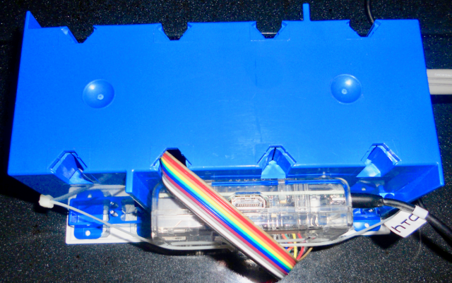
And finally, some tie wraps and packaging tape to attach the Raspberry Pi to the outside of the electrical box. Note that this assumes that we are not going to place this box anyplace where physical damage or stress is likely to occur. As can be seen above, there is really nothing protecting the ribbon cable, but that’s okay for us because the box isn’t going to be moved around once it’s where we need it. If there were any serious risk of the ribbon cable being damaged or pulled, we might have tried to use some additional protection, such as using silicone sealant/caulk at the hole where the ribbon cable enters the box, and/or wrapping the cable in some kind of protective sheath.
How we built it:
We drilled a ¾” hole in the side of the electrical box for the clamp, making sure to place it so that it would not interfere with mounting the outlets but also so that when tightening down the retaining nut there would not be a box rib in the way. You can see in one of the photos above where we placed it. We suggest taping a piece of masking tape over the box prior to drilling and then drilling through the tape – this will keep the drill point from wandering and also help avoid any possibility of the box cracking. We did need to work the drill around just a little bit to enlarge the hole slightly before the clamp would go through (a round file could also be used).
We stripped the insulation off the ends of three wires of the power cord, twisted the strands of each wire so they would be less likely to fray, and carefully passed the cord through the clamp and tightened the clamp to hold the cord in place. When doing this we found that we had to pass a bit more through the clamp than we originally thought, because not having quite enough made it very difficult to make connections.
We then took a length of leftover electrical cable containing #14 wire (14/2 with ground) and removed the individual wires to use for wiring the outlets. We took the bare ground wire and ran it from ground terminal to ground terminal (the green screws) on each of the outlets, and connected that to the green ground wire of the power cord using an orange wire nut. When doing this we were careful not to leave too much excess in the loop from outlet to outlet, since we didn’t want the bare ground wire getting anywhere near the relays.
We also ran the white wire from the nickel (silver) colored screws on each outlet to the white wire of the power cord. We stripped the insulation in such a way that we could run one wire from outlet to outlet and then connect it to the power cord using an orange wire nut, but you could as easily run a separate wire from one of the nickel colored screws of each outlet and connect them all together with the white wire from the power cord using a red wire nut. As long as the break off tab on the side of the outlet where the white wire connects has not been broken off, only one connection to one of the nickel colored screws on each outlet is necessary.
Then we cut about a five inch long piece of black wire for each brass colored screw (eight wires in total) and connected them to the brass colored screws on the outlets. Once again, remember that we had to break the tab that connects the brass colored screws together at each outlet, so that each outlet can be controlled separately. These wires are a bit tricky to prepare because one end must have enough of the insulation stripped enough to loop around the screws on the outlets, while the other end must be stripped just enough to fit under the screw terminals on the relay board, preferably without leaving much excess bare copper showing. These wires connect to the normally open terminal of each relay.
In addition we prepared 8 wires about 4½ inches long, with one end stripped to go into a wire nut, and the other stripped just enough to connect to the relay board. These wires connect to the center terminals of each relay.
The basic wiring of a single outlet is shown here. This only shows two of the relays, and we simply duplicated this when connecting the other outlets to the other relays:

The colors indicated are the colors of the electrical cord coming into the box, although we actually used black wires for all our connections to the relay contact terminals – we only used red wires in this illustration to make it obvious which wires connect to the black (hot) wire of the cord. As it happened, the cord we used did not color code the neutral and hot wires, so we (VERY CAREFULLY!!!) used a voltmeter to determine which was the hot wire – it was the one that gave us a reading of standard household voltage (usually 110 to 120 volts in the USA and Canada) relative to the ground wire. Of course we had to be very careful not to let any of the exposed wires touch each other, or us or any other object (other than the voltmeter probes) when doing this test. And of course this assumed that our household outlets are wired correctly.
There are a couple of other ways we could have determined which is the hot wire in a flat cord such as the one we used. A close examination of an outlet such as the one pictured above shows that the two rectangular slots are slightly different lengths. The shorter of the two is the hot side of the line, and you can see that the black wires to the relays are connected to that side in the above illustration. If you can see which wire of the cord would be connected to the prong of the plug that would go into that shorter slot, if the plug were plugged into that outlet, then you know which is the hot wire of the cord. Another way to determine which wire is which may be to use the sense of touch – if one of the wires has small ribs or grooves in it, that’s the neutral wire, while the opposite side of the cable would be the hot wire. Again, we’re assuming electrical standards used in the USA and Canada here; cords may well be different in other parts of the world.
After we had all the power cord and all the outlets and relays connected, but before we stuffed everything into the box, it looked like this:

Here’s another view:

You may note that there are two red wire nuts. We found that it was impossible to fit nine wires (the eight going to the relays plus the hot wire of the power cord) under a single wire nut, so under one wire nut we connected four of the wires that connect to the center screw terminals of the relays, and a short jumper wire. Then, under the other wire nut we connected the other four wires that connect to the center screw terminals of the relays, the other end of the jumper wire, and the hot wire from the power cord.
Just as an aside, we wonder why the manufacturers of these relays don’t offer a model where only one connection is needed to feed power to all the center terminals of all the relays? It would save a lot of time if such a model were available, and it would probably be a lot safer as well since we’d have fewer total connections to make.
Connecting the relay board to the Raspberry Pi:
Once all the power connections are made and everything is secure, before carefully stuffing everything into the electrical box we connected the ribbon cable to the relay board. We needed ten wires with female connectors on both ends. Near the center of the relay board, on the opposite edge from the relay contact connections, there should see a ten pin strip labelled as follows:
GND IN1 IN2 IN3 IN4 IN5 IN6 IN7 IN8 VCC
We simply connected the ten wire ribbon cable up in straight sequence (no criss-crossing wires or anything like that) and made a note of which color wire connected to GND, and which connected to VCC. Other may prefer to use specific colors with specific pins, but we just found it easier to not mix up the order of the wires. Once the ribbon cable is connected and routed out of the box through one of the knockout holes (see the pictures above) we were able to get the relay board and all the wiring stuffed into the box. We tried to get the relay board as close to the bottom of the box as possible, which meant we had to carefully bend the black wires to allow that to happen, but we also had to keep in mind that the relay board is rather fragile and to not put too much pressure on the board itself. As we were pushing the board down we could gently pull more of the ribbon cable out of the knockout hole. We took a little time with this process because if we had just tried to jam the relay board into the box there’s a good chance it would either have broken, or would not have pushed all the way down to the bottom of the box. We especially wanted to make sure that the bare ground wires could not touch the relay board, particularly the relay screw terminals, since that would have probably caused a rather spectacular flash as the electricity short-circuited! And also, we wanted to keep a little distance between the relay board and that metal clamp that holds the power cord in place, since the last thing we wanted was the hot side of the electrical line touching that clamp – that would be an electrocution hazard waiting to happen!
When pulling the ribbon cable out of the knockout hole we had to make sure that it didn’t bind, since we were essentially pulling it the wrong way through the hole, and also that we didn’t pull too much and bend the pins on the relay board.
Once we had everything into the box, we could connect the ribbon cable to the Raspberry Pi. This diagram attempts to show the way we connected the cable, though the colors picked for this illustration are completely arbitrary:

Here is how each of the pins on the relay board connected to the pins on the Raspberry Pi Model 1 that we used, starting with GND and ending with VCC:
GND to Pin 25 (GND)
IN1 to Pin 22 (GPIO25)
IN2 to Pin 18 (GPIO24)
IN3 to Pin 16 (GPIO23)
IN4 to Pin 15 (GPIO22)
IN5 to Pin 13 (GPIO27 or GPIO21, depending on model)
IN6 to Pin 12 (GPIO18)
IN7 to Pin 11 (GPIO17)
IN8 to Pin 7  (GPIO4)
VCC to Pin 2  (5 V)
This is what our ribbon cable actually looks like at the Raspberry Pi end:

You may wonder why we made the ribbon cable connections in what appears to be reverse order, for example using GPIO25 for IN1 and GPIO4 for IN8. The reason is that if you look at how we wired the outlets to the relay board, the leftmost outlet is actually wired to the relays associated with IN8 and IN7. So the lowest numbered GPIO actually controls the top left outlet, and the highest numbered GPIO controls the bottom right outlet. But also, it makes the ribbon cable connections a little neater at the Raspberry Pi, because the connections for +5 V and GND are at the right ends of the cable.
As for why we used the particular GPIO ports that we did, we chose to use only the eight GPIO pins that cannot be used for other purposes. While there are additional GPIO pins on the Raspberry Pi, the ones we did not use can be used for other purposes. If you look at this Raspberry Pi Pinout Diagram, we used the pins that are color coded green.
Here’s one more picture we took just before installing the cover plate over the outlets. You can’t really see it but the relay board fits nicely in the bottom of the box, and since this box is not going to be moved around we figured the stiffness of the #14 solid copper wires would be sufficient to hold the board in place. If the box were going to be subjected to vibration or movement, we would have mounted the relay board to the bottom of the box with screws and standoffs, and maybe covered the relay screw terminals with some kind of insulating material after all the connections were made, or at least used a strip of good quality electrical tape across the tops of the screw terminals. If we were to ever attempt to build such a unit for someone else to use, we would certainly make some attempt to secure the relay board to the bottom of the box, but realistically given the light weight of the relay board and all those #14 copper wires holding it in place, and the way it fits in the bottom of the box, we seriously doubt it’s going anywhere.

In case you are wondering, we did decide to have the main power plug for the unit, and the Raspberry Pi’s power supply, plug into separate outlets rather than trying to cram the Raspberry Pi’s power supply inside the electrical box and somehow attempt to safely connect it to the power cord. While it is certainly possible to do something like that, we don’t like cramming too much inside the box and we don’t have a problem with plugging the Raspberry Pi into a separate power strip that has a built in surge suppressor. Also, the power supply we used with a Raspberry Pi might fail someday, and it would be far more difficult to replace a failed power supply if we had to partially disassemble the unit to get to it.
We just want to note once more that the maximum load that can be connected to any one outlet is 10A, since that’s all the relay contacts are rated for. Using the formula volts X amps = watts, that means that if the household voltage is 110V then we can only connect a maximum of 110 volts X 10 amps = 1100 watts of purely resistive load. A purely resistive load would be something like incandescent lights, or a small heater with no fan or any other kind of motor. However, motors, transformers, and other inductive loads can draw many times their rated current for a split second during startup – this is why the lights may dim momentarily when any appliance with a large motor starts up. So, when connecting an inductive load, it probably should not draw anywhere near that 1100 watts maximum. A desktop computer is probably safe – normally they don’t draw anywhere near the wattage rating of their power supplies, unless perhaps a lot of peripherals are attached. But we would not even think of trying to control a window air conditioning unit with one of these – that would at the very least fry the relay contacts in a fairly short time.
And also, the maximum overall rating of connected equipment to ALL of the outlets cannot exceed the current-carrying capacity of the power cord, nor the circuit that the device is plugged into. The power cord we used has #14 wires, so it would handle 15A, or about 1650 watts (110 volts X 15 amps) safely. If we had a power cord with #12 wires, it could handle up to 20A, or about 2200 watts, but it’s fairly rare to find an AC power cord with #12 wires.
One more time, we want to emphasize that all of the above is what we did. We are NOT suggesting or implying that you should do what we did. If you choose to attempt to emulate what we did, YOU and YOU ALONE are responsible for the results, be they good or bad. Please re-read the cautionary paragraphs at the beginning of this article, and don’t even think of trying to emulate what we did if you are not absolutely certain that you can do it safely.
Controlling the outlets
Assuming that Raspbian has been installed on the Raspberry Pi, and that it has been configured using raspi-config, it is fairly easy to control the GPIO pins on the Raspberry Pi. Unfortunately many sites will tell you to install a lot of unnecessary software. A prime example is something called WiringPi, which is written in the C language. Anyone that has used it before and is comfortable with it can certainly use it for this type of project, but it’s overkill because the GPIO pins can be controlled perfectly well using simple bash scripts. And besides, WiringPi has been deprecated by the author.
There is one set of scripts that should go into the Pi’s root directory, since they must be run as root (or using sudo). Anyone can download these scripts using this link (click the “Download” button). The procedure would then be to copy the root_dir_gpio_scripts.zip file to the Raspberry Pi, and then move the scripts into the root directory and make them executable using these commands (replace /path/to/ with the actual path to the downloaded zip file):
sudo su
cd /root
unzip /path/to/root_dir_gpio_scripts.zip
chmod +x gpio*.sh
Feel free to examine the scripts using any standard text editor if you like, then enter
exit
to stop being the root user. These scripts can be run on their own to control the GPIO pins. For example, entering
/root/gpio4.sh on
should turn on the outlet associated with GPIO4, or
/root/gpio4.sh off
should turn that same outlet off. The other available options are toggle, which will turn the outlet on if it is currently off, or off if it is currently on, or reboot, which will turn off the outlet for 30 seconds and then turn it back on. If 30 seconds is too long to wait, the “sleep 30” command in each of the scripts could be changed to a more preferable time delay.
Please note that scripts are included for both GPIO21 and GPIO27, since some Raspberry Pi’s assign Pin 13 as GPIO21 and some as GPIO27. One or the other should control pin 13 of the Raspberry Pi. It is safe to delete whichever of the two does nothing on a particular Raspberry Pi.
While controlling the outlets using these scripts is possible, it can get a bit cumbersome, especially since the user would have to remember which outlet (and the device plugged into that outlet) is controlled by which GPIO pin. Fortunately, there’s an easier way, though it does depend on the scripts from the root_dir_gpio_scripts.zip package having been installed correctly. It begins with downloading the script from this link. The procedure is the same as for the previous zip file, except this installs to the user’s home directory. So do this:
cd ~
unzip /path/to/powercontrol.zip
chmod +x power.sh
The script is run by entering:
./power.sh
Or if that’s too much effort, this line can be added to the end of the user’s .bashrc file:
alias power="/home/pi/power.sh"
After that, simply entering the word power at a command prompt should be sufficient to run the script. One thing to note about the power.sh script is that it assumes the use of GPIO27 rather than GPIO21 for Pin 13. If the Raspberry Pi uses GPIO21 to control Pin 13, then run this to change the GPIO designation in the script:
sed -i -e 's/27/21/g' ~/power.sh
When you run the power.sh script you should see something similar to this:
PowerPi Control

Outlet 1 (Outlet 1) is currently ON
Outlet 2 (Outlet 2) is currently OFF
Outlet 3 (Outlet 3) is currently ON
Outlet 4 (Outlet 4) is currently OFF (UNINITIALIZED)
Outlet 5 (Outlet 5) is currently OFF (UNINITIALIZED)
Outlet 6 (Outlet 6) is currently OFF
Outlet 7 (Outlet 7) is currently ON
Outlet 8 (Outlet 8) is currently OFF

Enter action to take (On, Off, Reboot, Toggle, or Rename) followed by outlet number, for example OFF 1 or ON 2. You can also enter QUIT or EXIT:
As you can see, it will show the state of each outlet at the time the script is run. There are three possible states: OFF (UNINITIALIZED), OFF, and ON. An outlet that is OFF will only have the (UNINITIALIZED) after it if no commands have been sent to it since the last reboot. (UNINITIALIZED) is only an informational tag; the outlet is still off.
Note that Rename n (where n is an outlet number) can be used to change the name associated with an outlet, which is what is shown between the parentheses on each line. It’s also possible to change the outlet name manually by editing the contents of the associated outletnamen file, which is in the same directory as the power.sh script.
The scripts above can be run from a terminal window on the Raspberry Pi itself, or through a ssh connection from another machine on your local network. If you find you cannot ssh into your Raspberry Pi, run sudo raspi-config and then select “5 Interfacing Options Configure connections to peripherals“, and then select “P2 SSH Enable/Disable remote command line access to your Pi using SSH” and enable ssh access from there.
Anyone could write their own software to control this board, and it’s certainly possible to call the gpion.sh scripts from other scripts or software. However, one thing we found is that apparently the logical signals received by the relay board do the opposite of what might be expected. In other words, when a GPIO pin is at logical zero, the associated relay will turn on, and then when that GPIO pin goes to logical 1, the relay will turn back off. The scripts we used take this into account, but other Raspberry Pi GPIO pin control software might not. Therefore, if other software is used, it could return a false indication of the current state of the relays, or controls might do the opposite of what is expected.
We hope this article gives someone the inspiration to make something better than what we made! Once again, please be safe when working with electricity, and seek expert assistance if you don’t know what you’re doing!

This is amazing! Thank you for posting this. It’s just the inspiration I needed for a home automation project I’ve been wanting to do. Thank you!
A few questions – Can I do the same setup and use GFCI outlets over regular ones? Also, is there anyway to do this project to include 10-12 outlets? I think the Pi would only be capable of controlling 8 but could I set it up so that 8 would be smart outlets and 2-4 would be always on?
We don’t see any reason you couldn’t use GFCI outlets other than that you would not be able to “split” the two outlets like you can with a normal duplex outlet, so both outlets on the GFCI would be controlled by a single relay. While there are two brass screws on a GFCI, one of them is intended for feeding “downstream” outlets that are also controlled by the GFCI. Rather than spending all that money on GFCI outlets, you’d be further ahead to invest in a GFCI cord, of the type used on pressure washers, hair dryers, pool pumps, etc. Amazon sells several, and as long as you get one with a high enough amperage rating (we’d strongly recommend you get one rated for at least 15 Amps), that one plug should be able to provide GFCI protection for all your outlets. Then you can use the far less expensive standard outlets, and use the split wiring so each outlet is controlled by a separate relay. Of course, another option would be to replace the outlet you are plugging into with a GFCI outlet, which I’d definitely consider unless you intend this to be something you can move around to different places as needed (requisite safety reminder: Remember to ALWAYS shut off the power to any outlet before replacing it, and if you have any doubts whatsoever about your ability to replace an outlet and do it according to code, consult a licensed electrician!).
Theoretically a Pi could control more than 8 outlets but you’d need another relay board (they come in 2, 4, and 8 relay configurations, we believe), and you’d need to find out which additional pins can act as GPIO pins. We have never attempted to build one with more than 8 outlets, though, so have no experience with that. And you do have to be mindful of the maximum amperage rating – those relays can only handle 10A each, and your cord will probably max out at 15A (as might the circuit and/or outlet you’re connecting to).
Fantastic build! You mentioned, “If we were to ever attempt to build such a unit for someone else to use…” and I have to ask, WOULD you consider building one of these for someone else? It’s exactly what I need for a project, and while I’ve certainly done some wiring in the past, I wouldn’t say it’s my bread & butter. If you would ever do that, what price range would you charge? (note: in this hypothetical, your buyer might already have their own RPi Zero, so all that’s needed is the box + internals with the ribbon cable feeding out of it.)
Not a chance, because it would be illegal for us to do so where we live. People have quite a bit of latitude to do things like this for their own use (but please note we are not suggesting or implying that it’s even fully legal to build one for your own use, because electrical codes and requirements can vary from place to place and also because we are not lawyers). You might even get away with building something like this for another member of your family because you know they won’t rat you out to any government agency, or sue you if it doesn’t meet their expectations or if something bad happens. But building one for some stranger on the Internet is not a risk we’d ever be willing to take.
Yet another problem is we have found that those relay boards sometimes are sold with a bad relay, or that a relay sometimes goes bad shortly after the board is put into use, and we would not want to deal with that if it happens.
The biggest issue is that because it is an electrical device it cannot be sold without CSA or UL or similar certification, which involves an entire process that we understand is both expensive and time consuming. We have no idea what the actual cost would be to get those approvals, but we are pretty certain that it’s more than you’d want to pay (if you are that wealthy, maybe you can hire a licensed electrician to build one for you, assuming they would not have the same objections that we do).
Is it really crappy that the laws are structured in such a way that only corporations (or individuals with deep pockets) can build devices like this for sale to others? Yes, it is. And in some countries of the world we are sure that is not the case, but we don’t happen to live in one of those countries.
That’s fair! I had no idea the legality was so complicated, and I appreciate your explanation. If someone were going to build and sell these things for a living, I’d definitely want them to be well-regulated and certified, too.
shouldn’t you be using the JD-Vcc pin to take advantage of opto isolation?
https://electronics.stackexchange.com/questions/505318/how-to-properly-use-a-relay-module-with-jd-vcc-from-arduino-raspberry
Pete, would you care to elaborate on this, perhaps by providing a clear and easy to understand diagram of what you think should be done differently? As we said in the article, we used what worked for us, and we wired it based on other articles and videos we found on the web at the time that used the same relay boards. We are not electronic engineers. We have built a few of these units and they have all worked, although we have experienced relay failure of individual relays in a couple of cases, which we attributed to the boards being made inexpensively using components that are perhaps not always of the highest quality.
As for the link you provided, that is a classic case of something that is much too long and detailed to be useful. Not to mention that it is written in such a way that it’s probably only understandable by people who are really into electronics. If you understand it, that’s great, but it’s not at all helpful to just provide that link because the majority of out readers most likely won’t understand any of it. In case the name of our blog didn’t tip you off, we’re not really into complicated technical info, and the only reason I am leaving your post up is in the hope that you (or maybe someone else who happens to read and understand that ponderous web page) will explain precisely what it is that you think we should have done differently, and why.
I’m not an engineer or pro. I started out wanting to build a relay controlled by a raspberry pi. I watched a bunch of videos, read a few articles including yours and the one I linked to. I decided the best and safest
(and inexpensive) route is to use a wireless power outlet controlled by a raspberry pi and a 433Mhz transmitter and receiver.